Rubber Fender Installation Guide
Date:2025-10-20
Rubber fenders are essential for port and vessel berthing safety. Proper installation ensures stable energy absorption and extended service life. This guide provides a complete, standardized procedure — from preparation to inspection.
I. Preparation Before Installation
1. Fender Model Confirmation
- Confirm the rubber fender type according to the design drawings, ensuring it matches the vessel capacity. For example, the SC2500 model is suitable for 5,000–8,000 DWT vessels, capable of absorbing the designed berthing energy. Different fender models correspond to different energy absorption levels — selection must strictly follow design specifications.
- Inspect the rubber fender surface for cracks, bulges, or exposed fabric cords, especially within 3 cm of the bolt holes.
2. Tools and Materials Checklist
| Category | Items |
|---|---|
| Fixing Tools | Electric drill (M20 bit), torque wrench (up to 300 N·m), stainless steel expansion bolts (Grade 316) |
| Measuring Tools | Laser level, tape measure (accuracy ±1 mm/m) |
| Auxiliary Materials | Epoxy joint sealant (salt spray–resistant), rubber pads (Shore A 70 ± 5) |
3. Installation Environment Requirements
- Concrete foundation strength must be ≥ C40, curing age ≥ 28 days, and surface flatness ≤ 3 mm per 2 m.
- For tidal areas, installation should be carried out during low tide. Installation is prohibited when the tidal difference exceeds 2 m.
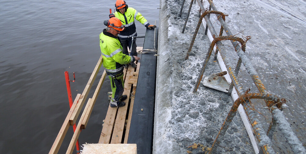
II. Standardized Installation Procedure
Step 1: Positioning and Marking
Use a total station to locate the fender’s longitudinal axis (tolerance ±5 mm).
Mark the bolt center positions; the spacing deviation between adjacent holes should not exceed ±1.5 mm.
A positioning template is recommended for precision.
Step 2: Embedded Plate Preparation
Clean surface rust from the embedded steel plate to Sa 2.5 cleanliness (sandblasting recommended).
Apply zinc-rich primer (dry film thickness ≥ 80 μm).
Attach a 3 mm rubber pad between the fender and the steel plate for sealing and cushioning.
Step 3: Fender Fixing
(1) Mechanical Fixing Method (Recommended)
This method ensures reliable anchoring and even load transfer.
- Initial tightening: 50% torque (150 N·m)
- Secondary tightening: 80% torque (240 N·m)
- Final tightening: 100% torque (300 N·m ± 5%)
Drill Φ22 mm holes (depth ≥ 120 mm) through the bolt holes, insert 316 SS expansion bolts, and tighten diagonally in three stages.
(2) Adhesive Fixing Method (For Special Conditions)
- Used when concrete surface unevenness exceeds 5 mm.
- Inject two-component epoxy adhesive (tensile strength ≥ 18 MPa), then apply uniform pressure for 24 hours with a load of ≥ 1.5 t/m².
Step 4: Sealing Treatment
Apply polysulfide sealant (thickness ≥ 3 mm) on bolt heads.
Fill the gaps between fender and concrete with PU foam sealant (expansion ≈ 300%) to form a continuous waterproof barrier.
III. Key Control Points
1. Mechanical Performance Verification
- Mechanical performance testing ensures reliability after installation.
- Static Load Test
Apply 1.25 × design reaction force for 15 minutes — no displacement allowed.
- Dynamic Load Test
Simulate berthing energy using E = 0.5mv² × 1.1.
- Testing Schedule:
Perform within 72 hours after installation.
2. Deformation Monitoring
- Measure fender compression after 7 days and 30 days; deformation must not exceed 5% of the free height.
- Use a laser distance meter for precise readings.
3. Corrosion Protection Enhancement
- For tidal or splash zones, install sacrificial anodes (e.g., aluminum alloy, 2.5 kg/m) to prevent electrochemical corrosion.
IV. Common Issues and Solutions
| Problem | Cause | Solution |
|---|---|---|
| Problem Cause Solution Cracks around bolt holes | Stress concentration during drilling | Enlarge the hole, fill with epoxy mortar, and reinforce with carbon fiber wrap |
| Local bulging of fender | Misaligned internal cord layers | Replace the entire fender (partial repair not allowed) |
| Corrosion of anchoring bolts | Chloride ion infiltration causing electrochemical corrosion | Use titanium alloy bolts and apply cathodic protection |
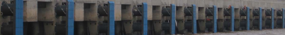
Next: Hanzhuang Port equipped with our 68 sets 400H of V type fenders
RELATED
- Dredging Pipeline Systems: Floating, Submerged, and Land Pipelines
- Nanjing Deers New Supply of DD Fenders to Vietnam
- How to Select the Right Marine Fender System for Ports and Terminals
- Supply Cell and Arch Fender Systems for Nantong Port’s 100,000 DWT Grain & Oil Berth Project
- Supply of Welded Dredge Ball Joints to a New European Client
- Causes and Countermeasures of Floating Dredging Pipeline Bursting
- H200mm DD fenders were delivered to a Client in Pakistan
- How to Accurately Provide Dimensions for Tugboat Fenders